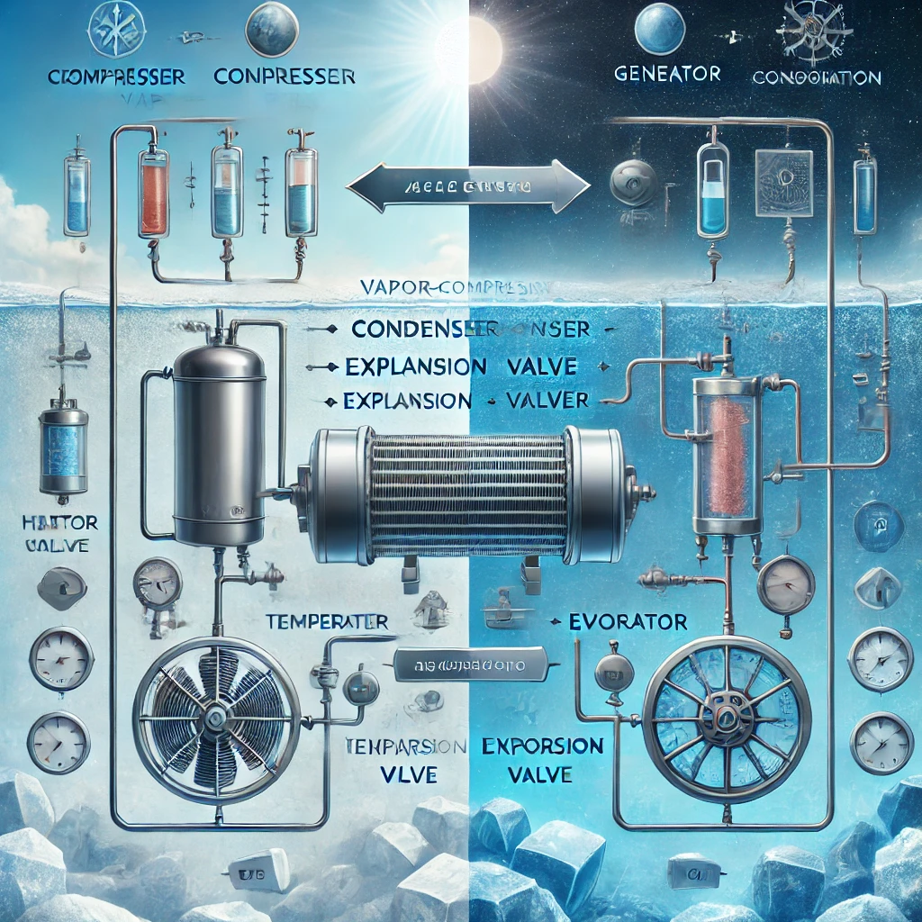
Refrigeration is an essential process in many fields, from household appliances to large-scale industrial systems. Among the various refrigeration methods, two fundamental cycles stand out: the Vapor-Compression Refrigeration Cycle and the Absorption Refrigeration Cycle. Understanding these cycles is crucial for designing efficient systems, especially as the world moves toward energy-efficient and sustainable solutions.
In this blog, we’ll explore these two refrigeration cycles in detail, with accompanying formulas and thermodynamic principles.
1. Vapor-Compression Refrigeration Cycle
The Vapor-Compression Cycle is the most widely used refrigeration process in both domestic and commercial systems, from air conditioners to refrigerators. It works on the principle of removing heat from a low-temperature environment and releasing it into a higher-temperature one using mechanical work.
Key Components:
- Compressor
- Condenser
- Expansion Valve
- Evaporator
Working Process:
The vapor-compression cycle operates in four stages, which can be represented on a Pressure-Enthalpy (P-h) diagram. Each step corresponds to a thermodynamic process:
- Compression (1→2):
- In the compressor, the refrigerant is compressed, raising its pressure and temperature.
- The refrigerant is in a vapor state after the evaporation process and is superheated.
- Isentropic Compression:
The process is assumed to be isentropic (constant entropy), and the work done on the refrigerant is expressed as: Wcomp=h2−h1W_{\text{comp}} = h_2 – h_1Wcomp=h2−h1 where h1h_1h1 and h2h_2h2 are the enthalpies before and after compression, respectively.
- Condensation (2→3):
- The high-pressure, high-temperature vapor enters the condenser, where it loses heat to the surroundings and condenses into a liquid.
- This phase is isobaric, meaning it occurs at constant pressure.
- The heat rejected in the condenser is: Qcond=h2−h3Q_{\text{cond}} = h_2 – h_3Qcond=h2−h3 where h3h_3h3 is the enthalpy after condensation.
- Expansion (3→4):
- The high-pressure liquid passes through the expansion valve or throttling device, where its pressure drops suddenly.
- The process is isenthalpic, meaning enthalpy remains constant.
- The temperature of the refrigerant drops as it expands into a low-pressure liquid-vapor mixture.
- Evaporation (4→1):
- The low-pressure, low-temperature refrigerant enters the evaporator, where it absorbs heat from the surroundings.
- The refrigerant evaporates and turns back into vapor, completing the cycle.
- The heat absorbed in the evaporator is: Qevap=h1−h4Q_{\text{evap}} = h_1 – h_4Qevap=h1−h4 where h1h_1h1 is the enthalpy after evaporation.
Coefficient of Performance (COP):
The COP is a measure of the cycle’s efficiency. For refrigeration, it is defined as the ratio of the cooling effect to the work input:COP=QevapWcomp=h1−h4h2−h1COP = \frac{Q_{\text{evap}}}{W_{\text{comp}}} = \frac{h_1 – h_4}{h_2 – h_1}COP=WcompQevap=h2−h1h1−h4
2. Absorption Refrigeration Cycle
The Absorption Refrigeration Cycle is an alternative method that uses thermal energy (often from waste heat, solar energy, or natural gas) instead of mechanical work to drive the cycle. This system is commonly used in situations where heat is available, and electricity is scarce or expensive.
Key Components:
- Generator
- Absorber
- Condenser
- Evaporator
- Solution Pump
Working Process:
The absorption refrigeration cycle relies on a refrigerant and an absorbent (typically ammonia-water or lithium bromide-water systems). The basic steps in the absorption cycle are similar to the vapor-compression cycle but with key differences in how the refrigerant is manipulated.
- Absorption (1→2):
- The refrigerant vapor from the evaporator is absorbed into a liquid absorbent, forming a solution.
- Heat is released during this process.
- Pumping (2→3):
- The solution is pumped to high pressure using a pump (this requires minimal mechanical work).
- The work done by the pump is negligible compared to the compressor in the vapor-compression cycle.
- Work by pump: Wpump=V⋅(P2−P1)W_{\text{pump}} = V \cdot (P_2 – P_1)Wpump=V⋅(P2−P1) where VVV is the volume, and P2−P1P_2 – P_1P2−P1 is the pressure difference.
- Generation (3→4):
- The high-pressure solution is heated in the generator, separating the refrigerant from the absorbent.
- The refrigerant becomes vapor, while the absorbent returns to the absorber.
- Heat input in the generator: Qgen=h4−h3Q_{\text{gen}} = h_4 – h_3Qgen=h4−h3
- Condensation (4→5):
- The refrigerant vapor is condensed in the condenser, rejecting heat to the surroundings.
- The process is similar to the condensation in the vapor-compression cycle.
- Expansion (5→6):
- The refrigerant is throttled to a low pressure through an expansion valve, reducing its temperature and pressure.
- Evaporation (6→1):
- The low-pressure refrigerant absorbs heat from the evaporator, producing the cooling effect.
Coefficient of Performance (COP):
The COP for an absorption refrigeration cycle is given by:COP=QevapQgen+WpumpCOP = \frac{Q_{\text{evap}}}{Q_{\text{gen}} + W_{\text{pump}}}COP=Qgen+WpumpQevap
Since the work done by the pump is very small, the COP largely depends on the heat input in the generator.
3. Comparison of Vapor-Compression and Absorption Cycles
| Aspect | Vapor-Compression Cycle | Absorption Refrigeration Cycle |
|---|---|---|
| Driving Energy Source | Mechanical Work (Electricity) | Thermal Energy (Heat) |
| Key Component | Compressor | Absorber + Generator + Pump |
| Coefficient of Performance | Typically higher (3-6 for HVAC systems) | Typically lower (0.7-1.2) |
| Application | Domestic and commercial refrigeration | Industrial refrigeration, gas-powered refrigerators, solar cooling |
| Initial Cost | Moderate | Higher due to additional components |
| Operating Cost | Depends on electricity prices | Lower if waste heat or renewable energy is available |
| Complexity | Simple, fewer components | Complex, involves multiple heat exchangers |
Conclusion
Both the vapor-compression and absorption refrigeration cycles have their strengths and limitations. Vapor-compression systems dominate in everyday applications due to their higher efficiency and simpler design. However, as sustainability becomes more critical, absorption systems are gaining popularity, especially where waste heat or renewable energy is readily available.
Understanding these cycles is crucial for HVAC professionals, engineers, and sustainability advocates who are seeking to optimize energy efficiency and contribute to greener technologies.
Do you have any experience with either of these refrigeration cycles? Let me know in the comments below!


Your writing wraps around you like a warm blanket, providing comfort while challenging you to think deeper.
There is quiet continuity in your writing, where ideas accumulate slowly, creating rhythm, cohesion, and layered insight. The text encourages lingering attention, reflective engagement, and meditative immersion.